5 Basic Setup ( LHV5100 Series )
5.1 Step 1: Connect the BNC Cameras
-
Connect
Lorex
MPX or standard analog cameras to the Video Input ports on the rear panel of the DVR.
![Graphic]() Push and twist the BNC connector clockwise to secure it to the BNC port.
Push and twist the BNC connector clockwise to secure it to the BNC port.

5.2 Step 2: Connect the Mouse
-
Connect a USB mouse (included) to one of the USB ports.
![Graphic]()

5.3 Step 3: Connect the Ethernet Cable
-
Connect an Ethernet cable (included) to the LAN port on the rear panel of the DVR. Connect the other end of the Ethernet cable to a router on your network.
![Graphic]()

5.4 Step 4: Connect the Monitor
-
Connect the included HDMI cable from the HDMI port to the TV or monitor (recommended).
OR
-
Connect a VGA cable (not included) from the VGA port to the monitor.
![Graphic]()
- HDMI port.
- VGA port.

5.5 Step 5: Connect the Power Adapter and Power on the DVR
- Connect the included power adapter to the DC 12V port. Connect the end of the power adapter to a wall socket or a surge protector.
-
Turn the power switch to ON to turn on the DVR.
![Graphic]()

At startup, the system performs a basic system check and runs an initial loading sequence. After a few moments, the system
loads a live display view and prompts you to create a new, secure 6 character password.
5.6 Step 6: Creating a New, Secure Password
When using your system for the first time, you will be prompted to create a new, secure 6 character password.
- Enter a new, secure 6 character password for the DVR and click OK. Record your password and store it in a secure place, this password will be used to connect to your system from now on.
5.7 Step 7: Upgrade Firmware to Latest Version (if Available)
If a firmware upgrade is available, you will be asked to install it once the system starts up. It is required to upgrade your
system firmware and client software or mobile apps to the latest version to enable remote connection to the system.
- After startup, a notification will appear asking you to upgrade the firmware. Click OK to upgrade.
- Enter the system user name (default: admin) and your new, secure password.
- Click OK. Wait for the firmware update to complete. The system will restart once the firmware has been upgraded.
If a firmware upgrade is available:
5.8 Step 8: Verify Camera Image
- Power on the cameras, and then verify the camera video quality before mounting the cameras to a permanent location.
- Mount the cameras under a sheltered location. Always verify the outdoor rating of your camera before installing it in a permanent location.
- See 5.12 Connecting Cameras for connecting and installing Lorex MPX cameras.
5.9 Step 9: Set the Time
- Set the system time and date for accurate video time stamps. Videos with inaccurate times may not be valid as surveillance evidence.
- For details on setting the system time, see 9 Setting The Time .
5.10 Default System Password & Port Numbers
A user name and password is required to log in to the system. Use the new, secure 6 character password created during initial setup to access your system.
- Username: admin
- Password: Secure 6 character password created during initial setup.
Local system and remote connectivity (LAN & Internet) user name and password:
- Port 80 (HTTP port)
- Port 35000 (Client port)
Default system ports:
5.10.1 Lorex Cloud™
This system features the exclusive
Lorex Cloud™
. This is a cloud service that allows you to connect to your system over the Internet via a secure handshake with our servers.
This means you can easily connect to your system without requiring any network configuration.
- See 15 Connecting to Your System Using Smartphone or Tablet Apps .
For details on setting up your system to connect to the Internet using
Lorex Cloud™
:
5.11 Quick Access to System Information

5.12 Connecting Cameras
5.12.1 Camera Compatibility
This system is compatible with
Lorex
8MP (4K), 4MP (2K), 2MP (1080p), 1MP (720p), 960H, and standard analog
cameras. For a list of compatible cameras, please visit
www.lorextechnology.com
.
5.12.2 About Lorex MPX Cameras
Lorex
MPX cameras transmit high-definition video over BNC cable (such as RG59). They use analog signals and can transmit video
signals over long cable runs.
Lorex
MPX cameras use a proprietary analog standard that only works with
Lorex
MPX DVRs. MPX is not compatible with HD-SDI equipment.
5.12.3 Installing Cameras
- Test the cameras before permanent installation. Plan where you will route the wiring for the camera and where you will aim the camera.
- Mount the camera where the lens is away from direct and intense sunlight.
- Plan your cable wiring so that it does not interfere with power lines or telephone lines.
- Ensure that the camera wiring is not exposed or easily cut.
- Mount the camera in an area that is visible, but out of reach.
- Avoid pointing the camera at a glass window to see outside. This may result in a bright white ring in the night vision image, as the light from the night vision LEDs may reflect off the glass.
- Adjust the camera angle so that it covers an area with high traffic.
- In "high-risk" locations, have multiple cameras point in the same area. This provides camera redundancy if a vandal attempts to damage the camera.
Installation Tips
To install the cameras:
- Mount the camera(s) to the desired mounting surface according to the instructions that came with the camera(s). Choose a firm mounting surface.
- Adjust the camera stand to ensure that the camera has a satisfactory view of the area you would like to monitor. Stand configuration depends on the mounting surface you have chosen.
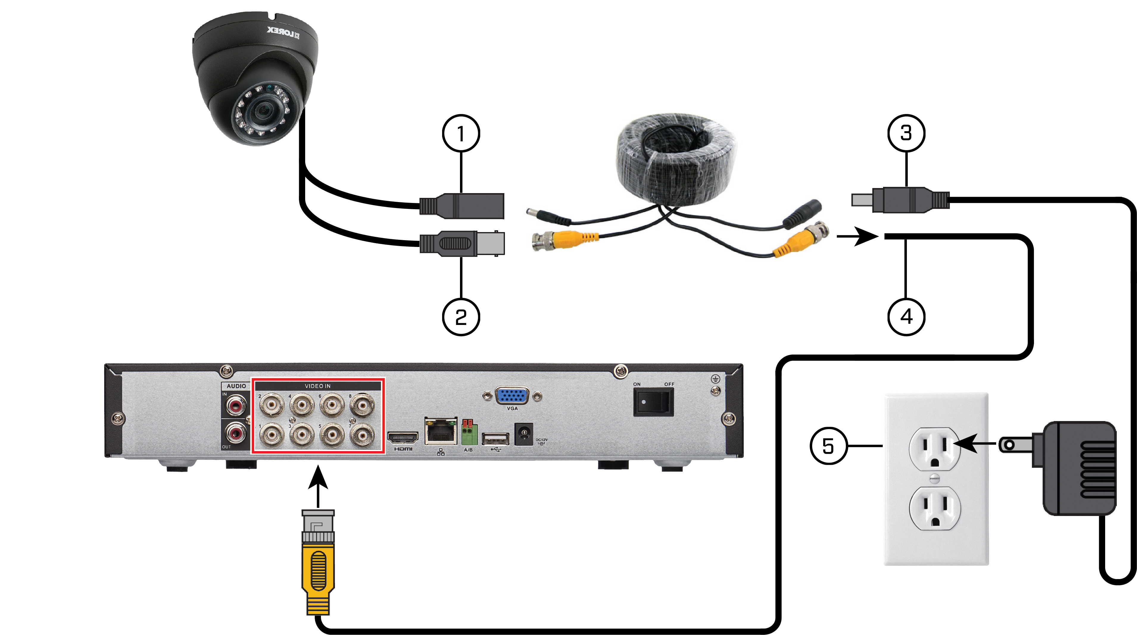
5.12.4 Connecting Camera Extension Cables
- Connect the male power connector on the BNC extension cable to the female power connector on the camera.
- Connect the BNC connector to the camera. See 5.12.4.1 Connecting and Removing BNC Cables for how to connect and remove BNC cables.
- Connect the female power connector on the BNC extension cable to the power adapter.
- Connect the BNC connector to one of the Video Input ports on the rear panel of the DVR.
- Plug the camera power adapter into a power outlet.
Camera Installation Diagram
5.12.4.1 Connecting and Removing BNC Cables
BNC (Bayonet Nut Connector) is a special connector that locks on to the system port and cannot be accidently removed.
- Push the BNC connector firmly into the BNC port and simultaneously twist the connector clockwise to tighten.
- To remove a BNC connector from a BNC port, push and simultaneously twist the connector counter-clockwise to loosen the BNC connector.
To connect or remove a BNC connector: