16 Using the Main Menu
-
From the Live View display, right-click to open the Quick Menu, then click Main Menu.
![Graphic]() OR
OR -
From the Live View display, hover the mouse near the bottom of the screen, then click
![icon]() on the Navigation Bar.
on the Navigation Bar.
![Graphic]()
To open the main menu:


16.1 Main Menu Overview

- Playback: Search for and play back recordings, or search for person and/or vehicle detection events. For full details, see 10 Playback .
- Backup: Export recordings and snapshots to a USB flash drive (not included). For full details, see 11 Backup .
- Camera: Open the menu to manage IP cameras connected to the network, set recording parameters, and assign custom titles for your cameras.
- Information: View system information.
- Settings: Configure general system settings, recording schedule, motion settings, and more.
- Shutdown: Logout, restart, or shutdown the system.
16.2 Camera Menu
The Camera Menu allows you to manage IP cameras, set recording parameters, and assign custom titles for your cameras.
16.2.1 Viewing Camera Status
View the connection and alarm status for all connected cameras.
- From the Live View display, right-click to open the Quick Menu, then click Main Menu.
-
Click
![icon]() , then click REMOTE DEVICE. Click the STATUS tab on the side panel.
, then click REMOTE DEVICE. Click the STATUS tab on the side panel.
![Graphic]()
To view camera status:

16.2.2 Camera Firmware Versions
View firmware versions for connected cameras.
- From the Live View display, right-click to open the Quick Menu, then click Main Menu.
-
Click
![icon]() , then click REMOTE DEVICE. Click the FIRMWARE tab on the side panel.
, then click REMOTE DEVICE. Click the FIRMWARE tab on the side panel.
![Graphic]()
To view camera firmware versions:

16.2.3 Upgrading Camera Firmware
You can update the firmware for connected IP cameras through the NVR. Firmware upgrades provide enhanced functionality for
the cameras. Typically, a camera firmware upgrade will not be necessary unless directed to do so by technical support.
- Download the camera firmware file.
- Extract the firmware file and copy it to a USB thumb drive (not included).
- Insert the USB thumb drive (not included) into a USB port on the system.
- From the Live View display, right-click to open the Quick Menu, then click Main Menu.
-
Click
![icon]() , then click REMOTE DEVICE. Click the IPC UPGRADE tab on the side panel.
, then click REMOTE DEVICE. Click the IPC UPGRADE tab on the side panel.
![Graphic]()
- Click Select. Select the firmware file on the USB drive and click OK.
- Check the cameras you would like to apply the upgrade to in the list and then click Start Upgrade.
To upgrade the camera firmware:

16.2.4 PoE Manager
View the status of IP cameras connected to the recorder, including video transmission speed and power drawn through PoE.
- From the Live View display, right-click to open the Quick Menu, then click Main Menu.
-
Click
 , then click REMOTE DEVICE. Click the POE MANAGER tab on the side panel.
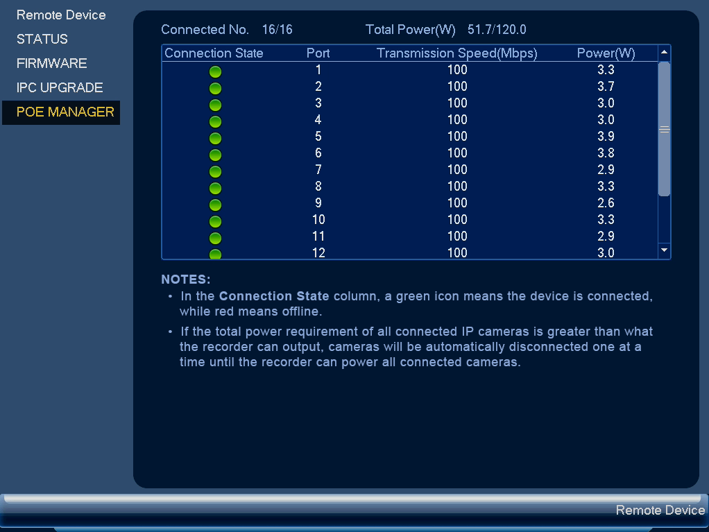
To view camera PoE status:
16.2.5 Configuring Snapshot Recording Settings
The system can be set to record snapshot images when a camera detects motion. These snapshots can be viewed through the Playback
menu or can be attached to email alerts and push notifications. Use the following procedure to set the snapshot parameters
for each camera.
- From the Live View display, right-click to open the Quick Menu, then click Main Menu.
-
Click
![icon]() , then click RECORDING. Click the Snapshot tab on the top panel.
, then click RECORDING. Click the Snapshot tab on the top panel.
![Graphic]()
- Under Snapshot, select the number of snapshots the system will take when the snapshot button is pressed.
-
Configure the following settings for snapshots saved automatically from motion detection or the snapshot schedule:
- Channel: Select the channel you would like to configure.
- Mode: Select Timing for the system to take snapshots at fixed intervals throughout the day, or select Trigger for the system to take snapshots only when triggered by motion detection (snapshot recording must be enabled in the motion detection menu - see 12 Motion Detection for details).
- Image Size: The image size is the same as the Main Stream resolution of the camera.
- Image Quality: Select the snapshot image quality between 1 (lowest) and 6 (highest)
- Interval: Enter the time between snapshots in seconds.
- Click OK to save changes.
To configure snapshot recording settings:

16.2.6 Configuring Video Overlay Settings
The Overlay tab allows you to configure the text and information that appears overtop of the camera image, such as time and
channel display.
- From the Live View display, right-click to open the Quick Menu, then click Main Menu.
-
Click
![icon]() , then click RECORDING. Click the Overlay tab on the top panel.
, then click RECORDING. Click the Overlay tab on the top panel.
![Graphic]()
- Under Channel, select the camera you would like to configure.
-
Configure the following settings:
- Time Display: Check to display the time information during live view. Click Set next to Time Display to choose the position of the time display overlay. Click-and-drag the time display to reposition it. Right-click when finished.
- Channel Display: Check to display the channel information. Click Set next to Channel Display to choose the position of the channel display overlay. Click-and-drag the channel display to reposition it. Right-click when finished.
- Cover-Area: Check to hide certain parts of the camera image in video recordings. Click the numbered boxes under the Cover-Area checkbox, representing the number of black boxes (masks) that will appear on the camera image. Click Set next to Cover-Area to choose the position of the mask overlay. Click-and-drag masks to reposition them, or click-and-drag the edges to resize a mask. Right-click to exit the live screen.
- Lorex Logo: Check to display a Lorex logo watermark on the selected channel. Click Set next to Lorex Logo to choose the position of the logo overlay. Click-and-drag the logo to reposition it. Right-click when finished.
- Click OK to save changes.
- (Optional) Click Copy to copy overlay settings to other channels.
To configure video overlay settings:

16.2.7 Creating Custom Channel Names
You can assign custom names to your cameras. For example, you can name your cameras based on their location (e.g. hallway
or front door).
- From the Live View display, right-click to open the Quick Menu, then click Main Menu.
-
Click
![icon]() , then click CHANNEL NAME.
, then click CHANNEL NAME.
![Graphic]()
- Click a channel to enter a custom name.
- Click Apply to save changes.
To create custom channel names:

16.3 Information Menu
View system information related to storage, network status, system warnings, and more.
16.3.1 Hard Drive Information
View information related to the hard drives installed in the system, including capacity, status, and type.

- From the Live View display, right-click to open the Quick Menu, then click Main Menu.
-
Click
![icon]() , then click INFO. Click the HDD tab on the side panel.
, then click INFO. Click the HDD tab on the side panel.
To access the HDD Info menu:
16.3.2 Recording Information
View start and end times of recordings saved on the hard drive.

- From the Live View display, right-click to open the Quick Menu, then click Main Menu.
-
Click
![icon]() , then click INFO. Click the RECORD INFO tab on the side panel.
, then click INFO. Click the RECORD INFO tab on the side panel.
To access the Record Info menu:
16.3.3 Fan and CPU Status
Configure fan speed setting and monitor system health.
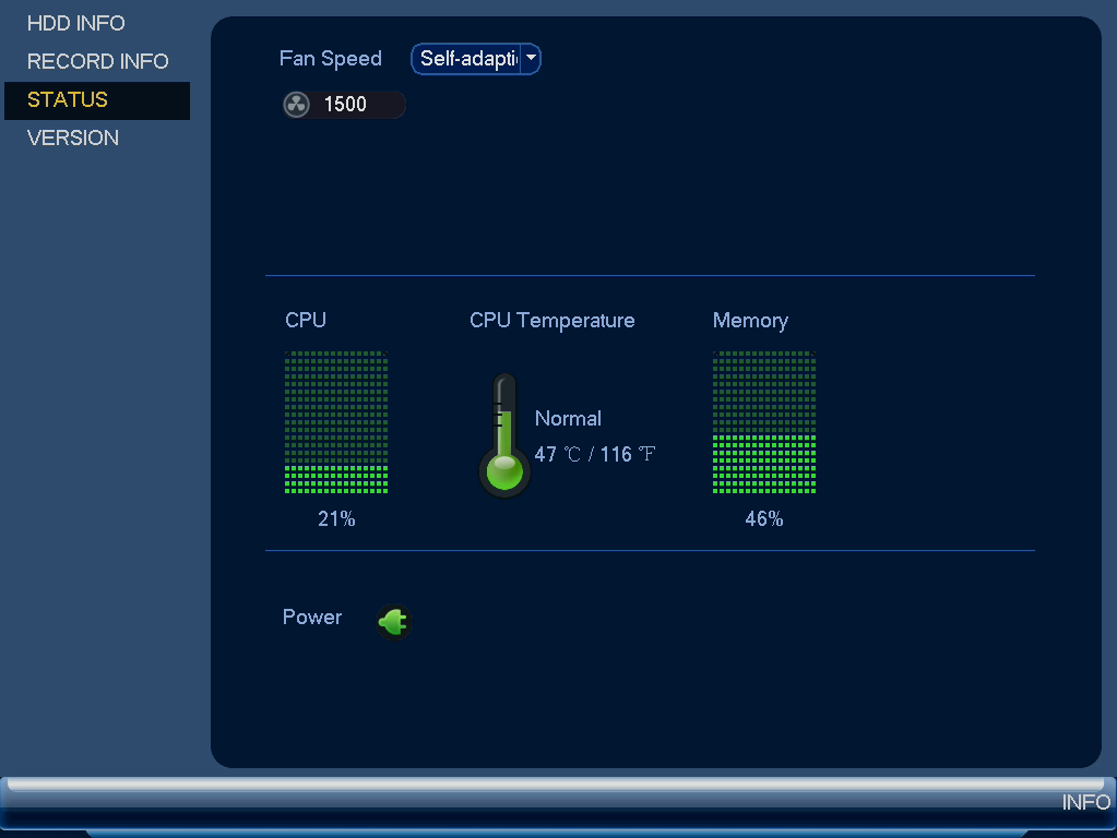
- From the Live View display, right-click to open the Quick Menu, then click Main Menu.
-
Click
 , then click INFO. Click the STATUS tab on the side panel.
16.3.4 Version Information
View system information such as device ID, model number, IP address, and firmware version.

- From the Live View display, right-click to open the Quick Menu, then click Main Menu.
-
Click
![icon]() , then click INFO. Click the VERSION tab on the side panel.
, then click INFO. Click the VERSION tab on the side panel.
To access the Version Info menu:
16.3.5 Event Information
View a summary of active system alarms. Activated alarms are highlighted in white. Additional info such as channels that are
currently detecting motion is shown.

- No HDD: No hard drive is detected.
- HDD Error: Hard drive error detected.
- Disk Full: Hard drive is full.
- IP Conflict: More than one device on the network is using the same IP address.
- Net Disconnect: System is not connected to the network.
- MAC Conflict: More than one device on the network is using the same MAC address.
- Video Loss: Shows disconnected channels.
- Motion Detect: Shows channels with active motion alarms.
The following alarms are shown in the Alarm Status menu:
- From the Live View display, right-click to open the Quick Menu, then click Main Menu.
-
Click
![icon]() , then click EVENT.
, then click EVENT.
To access the event information menu:
16.3.6 Online Users
View all users connected to the system using computers or mobile devices.

- From the Live View display, right-click to open the Quick Menu, then click Main Menu.
-
Click
![icon]() , then click NETWORK. Click the ONLINE USERS tab on the side panel.
, then click NETWORK. Click the ONLINE USERS tab on the side panel.
To access the online users menu:
16.3.7 Network Load
View network traffic your system is sending and receiving.

- From the Live View display, right-click to open the Quick Menu, then click Main Menu.
-
Click
![icon]() , then click NETWORK. Click the Network Load tab on the side panel.
, then click NETWORK. Click the Network Load tab on the side panel.
To access the network load menu:
16.3.8 Network Test
Test if your system can connect to other devices over the LAN or Internet. You can enter the IP address of a device and click
Test to determine if your system can connect to it.

- From the Live View display, right-click to open the Quick Menu, then click Main Menu.
-
Click
![icon]() , then click NETWORK. Click the TEST tab on the side panel.
, then click NETWORK. Click the TEST tab on the side panel.
To access the network test menu:
16.3.9 BPS
Shows bitrates of connected cameras. The bitrate is the amount of data the camera is sending to the system.

- From the Live View display, right-click to open the Quick Menu, then click Main Menu.
-
Click
![icon]() , then click BPS.
, then click BPS.
To access the BPS menu:
16.3.10 System Log
Search for system logs in a certain time range.

- From the Live View display, right-click to open the Quick Menu, then click Main Menu.
-
Click
![icon]() , then click LOG.
, then click LOG.
To access the log menu:
16.4 Settings Menu
Configure general system settings, recording schedule, motion settings, and more.
16.4.1 Selecting DHCP or Static IP Address (TCP/IP)
Configure IP address settings.
To configure IP address settings:
- From the Live View display, right-click to open the Quick Menu, then click Main Menu.
-
Click
![icon]() , then click NETWORK. Click the TCP/IP tab on the side panel.
, then click NETWORK. Click the TCP/IP tab on the side panel.
![Graphic]()
-
Check DHCP (recommended) to let the system automatically obtain an IP address from the router.
ORUncheck DHCP to assign a static IP address (advanced users only).
-
If you uncheck DHCP, configure the following:
- IP Version: Select IPv4 or IPv6.
- IP Address: Enter the IP address you would like to assign to the system. Make sure that no other device on your network is using the same IP address.
- Subnet Mask: Enter the subnet mask for your network.
- Default Gateway: Enter the gateway address for your network.
- Preferred DNS: Enter the address of your primary DNS server.
- Alternate DNS: Enter the address of your secondary DNS server.
- Click Apply to save changes.

16.4.2 Configuring System Ports (Connection)
Configure ports used by the system for remote connectivity. If you are using DDNS connectivity, port forwarding is required
for the HTTP Port (default: 80) and TCP (Client) Port (default: 35000).
To configure system ports:
- From the Live View display, right-click to open the Quick Menu, then click Main Menu.
-
Click
![icon]() , then click NETWORK. Click the Port tab on the side panel.
, then click NETWORK. Click the Port tab on the side panel.
![Graphic]()
- Configure the port numbers as needed.
- Click Apply to save changes.

16.4.3 Configuring IP Filter
Configure permissions for external IP addresses attempting to access the unit.
- From the Live View display, right-click to open the Quick Menu, then click Main Menu.
-
Click
![icon]() , then click NETWORK. Click the IP FILTER tab on the side panel.
, then click NETWORK. Click the IP FILTER tab on the side panel.
![Graphic]()
- Check Enable.
- Select Trusted Sites to add IP addresses or ranges that are permitted to access the recorder, or select Blocked Sites to add IP addresses or ranges that are not permitted to access the recorder.
- Click Add to enter an IP address or range.
- Click Apply when finished.

16.4.4 Configuring Email Alerts
You can configure the system to send out email alerts for motion detection or other events.
- From the Live View display, right-click to open the Quick Menu, then click Main Menu.
-
Click
![icon]() , then click NETWORK. Click the EMAIL tab on the side panel.
, then click NETWORK. Click the EMAIL tab on the side panel.
- Check Enable to enable email notifications.
To configure Email Alerts:
- Under Mail Select, select Lorex Mail to use the Lorex email server to send out alarm notifications. This is the recommended setting.
-
Configure the following:
- Email Schedule: Configure time periods during which email alerts will be sent.
- Receiver: Enter the email address that will receive alerts.
- Sender: Enter the sender’s email address.
- ALERT: Enter the subject line for the email alert.
- Attachment: Check to include an image attachment of the camera.
- Interval: Enter the interval between alert emails.
- Health Enable: Check to enable health check emails. Health check emails will be sent periodically to ensure that the system is functioning normally. Enter the interval in minutes for health check emails.
- Click Test to send a test email.
- Click Apply to save settings.
If you want to use Lorex’s email server (recommended):

- Under Mail Select, select Customize.
-
Configure the following:
- SMTP Server: Enter the SMTP server address.
- Port: Enter the port used by the SMTP server.
- Anonymous: Check if your server supports anonymous log ins. Otherwise, leave this unchecked.
- User: Enter the SMTP user name.
- Password: Enter the SMTP password.
- Receiver: Enter the email address that will receive alerts.
- Sender: Enter the sender’s email address.
- ALERT: Enter the subject line for the email alert.
- Attachment: Check to include an image attachment of the camera.
- Encryption Type: Select SSL or TLS if your server uses encryption. Select None if your server does not use encryption.
- Interval: Enter the interval between alert emails.
- Health Enable: Check to enable health check emails. Health check emails will be sent periodically to ensure that the system is functioning normally. Enter the interval in minutes for health check emails.
- Click Test to send a test email.
- Click Apply to save settings.
If you want to use your own email server (advanced):

16.4.5 FTP (Advanced)
Send recordings and/or snapshots to an FTP server.
- From the Live View display, right-click to open the Quick Menu, then click Main Menu.
-
Click
![icon]() , then click NETWORK. Click the FTP tab on the side panel.
, then click NETWORK. Click the FTP tab on the side panel.
![Graphic]()
- Check Enable to allow FTP connection, and select either FTP or SFTP depending on your configuration.
-
Configure the following:
- Host IP: Enter the FTP server’s address.
- Port: Enter the FTP port.
- Username: Enter your FTP username.
- Password: Enter your FTP password.
- Anonymous: Enable if your FTP server supports anonymous login.
- Remote Directory: Enter the directory to save recordings and/or snapshots to.
- File Length: Enter the recording file length in minutes.
- Image Upload Interval: Enter the interval between snapshots in seconds.
- Channel: Select a channel to set FTP recording preferences for.
- Weekday: Select a day of the week to configure FTP recording settings for, or select All to apply to all days of the week.
- Period: Select up to 2 periods of time where the system will save recordings to the FTP. Check Alarm, Motion, or Continuous beside each period to determine which recording type will be uploaded to the FTP.
- Click Apply.
To configure FTP settings:

16.4.6 Configuring Switch Settings (Advanced)
Configure the networking settings for the internal PoE switch.
- From the Live View display, right-click to open the Quick Menu, then click Main Menu.
-
Click
![icon]() , then click NETWORK. Click the Switch Settings tab on the side panel.
, then click NETWORK. Click the Switch Settings tab on the side panel.
![Graphic]()
- Configure the IP Address, Subnet Mask, and Default Gateway for the internal PoE switch.
- Click OK. Click Save to save changes. The system will restart.
To configure switch settings:

16.4.7 P2P Setting
The P2P Setting menu is used only to enable / disable remote access to the system using a P2P connection.
- From the Live View display, right-click to open the Quick Menu, then click Main Menu.
-
Click
![icon]() , then click NETWORK. Click the P2P tab on the side panel.
, then click NETWORK. Click the P2P tab on the side panel.
![Graphic]()
- Check Enable to use P2P, or uncheck to disable.
- Click Apply.
To change P2P setting:

16.4.8 Configuring Video Loss Settings
Configure video loss settings and how the system reacts to a video loss event. Video loss means that video from one or more cameras was interrupted or disabled. It could be caused by a number of factors, such as
a loose or damaged connection, loss of power to a camera, or a blocked camera lens.
- From the Live View display, right-click to open the Quick Menu, then click Main Menu.
-
Click
![icon]() , then click EVENT. Click the MOTION tab on the side panel, then click the Video Loss tab on the top panel.
, then click EVENT. Click the MOTION tab on the side panel, then click the Video Loss tab on the top panel.
![Graphic]()
- Under Camera, select the channel you would like to configure.
- Check Enable to enable video loss events for the selected channel.
-
Configure the following to customize settings for video loss events:
- Alarm Out: Check the box to activate alarm output devices (not included) when the selected channel loses video. Select the alarm output devices that will be activated when video loss occurs, then enter the number of seconds the alarm output device(s) will activate after video loss occurs next to Latch.
- Schedule: Click Set to configure a schedule for video loss events. It is recommended to leave this on the default setting, so you can be alerted at any time one of your cameras loses video.
- Show Message: Check to show a popup message on the monitor if one of your cameras loses video.
- Send Email: Check to enable email alerts. You must configure email alerts before you will be able to receive them (see 16.4.4 Configuring Email Alerts ).
- Record Channel: Click the checkbox to enable video recording when video loss occurs. You can then select the channels the system will record when video loss occurs on the currently selected channel.
- PTZ Activation: Check to enable PTZ actions when video loss occurs (PTZ camera required; not included). Click Set to select which PTZ actions will be taken by each camera.
- Post_REC: Enter the number of seconds the system will record after video loss occurs.
- Sequence: Check to enable a custom sequence mode when motion is detected on the selected channel. Then click the channels you would like to display in the custom sequence mode.
- Snapshot: Click the box to enable snapshot recording when video loss occurs. You can then select which channels will save snapshots when video loss occurs on the currently selected channel.
- Buzzer: Check to enable the system buzzer when video loss occurs on the currently selected channel.
- Click Apply to save changes.
To configure video loss settings:

16.4.9 Configuring Hard Drive Warnings
Hard drive warnings will notify you if an issue is detected with the hard drive.
- From the Live View display, right-click to open the Quick Menu, then click Main Menu.
-
Click
![icon]() , then click EVENT. Click the WARNING tab on the side panel, then click the HDD tab on the top panel.
, then click EVENT. Click the WARNING tab on the side panel, then click the HDD tab on the top panel.
![Graphic]()
-
Under Event Type, select the hard drive event you would like to configure. Check Enable to activate the selected warning.
- No HDD: No hard drive detected.
- Disk Error: A hard drive error has been detected.
- Disk Full: The hard drive is full or almost full. You can enter the percentage of disk space remaining that will trigger a warning under Less Than (e.g. when less than 10% of the hard drive is empty, trigger a warning). Disk Full warnings will not occur if overwrite is enabled.
- All: Configure warnings for all hard drive events.
-
Configure the responses the system will take when the selected event occurs:
- Alarm Out: Check the box to activate alarm output devices (not included) when the selected event occurs. Select the alarm output devices that will be activated, then enter the number of seconds the alarm output device(s) will activate after the selected event occurs next to Latch.
- Show Message: Show a popup message on the monitor.
- Send Email: Check to enable email alerts. You must configure email alerts before you will be able to receive them (see 16.4.4 Configuring Email Alerts ).
- Buzzer: Check to activate the system buzzer.
- Click Apply to save changes.
To configure hard drive warnings:

16.4.10 Configuring Network Warnings
Network warnings will notify you if there your system loses connection to the Internet or local network or if there is an
issue on your network.
- From the Live View display, right-click to open the Quick Menu, then click Main Menu.
-
Click
![icon]() , then click EVENT. Click the WARNING tab on the side panel, then click the Network tab on the top panel.
, then click EVENT. Click the WARNING tab on the side panel, then click the Network tab on the top panel.
![Graphic]()
-
Under Event Type, select the event type you would like to configure. Check Enable to activate the selected warning.
- Disconnect: The system has lost connection to the network.
- IP Conflict: More than one device on your network has the same IP address.
- MAC Conflict: More than one device on your network has the same MAC address.
- All: Configure responses for all network events.
-
Configure the following for the selected event type:
- Alarm Out: Check the box to activate alarm output devices (not included) when the selected event occurs. Select the alarm output devices that will be activated, then enter the number of seconds the alarm output device(s) will activate after the selected event occurs next to Latch.
- Show Message: Check to show a popup message when the selected event occurs.
- Send Email: Check to enable email alerts. You must configure email alerts before you will be able to receive them (see 16.4.4 Configuring Email Alerts ).
- Buzzer: Check to activate the system buzzer.
- Click Apply to save changes.
To configure network warnings:

16.4.11 Configuring Fan Warnings
Fan warnings will notify you if there is an issue with the system’s cooling fan.
- From the Live View display, right-click to open the Quick Menu, then click Main Menu.
-
Click
 , then click EVENT. Click the WARNING tab on the side panel, then click the Fan tab on the top panel.
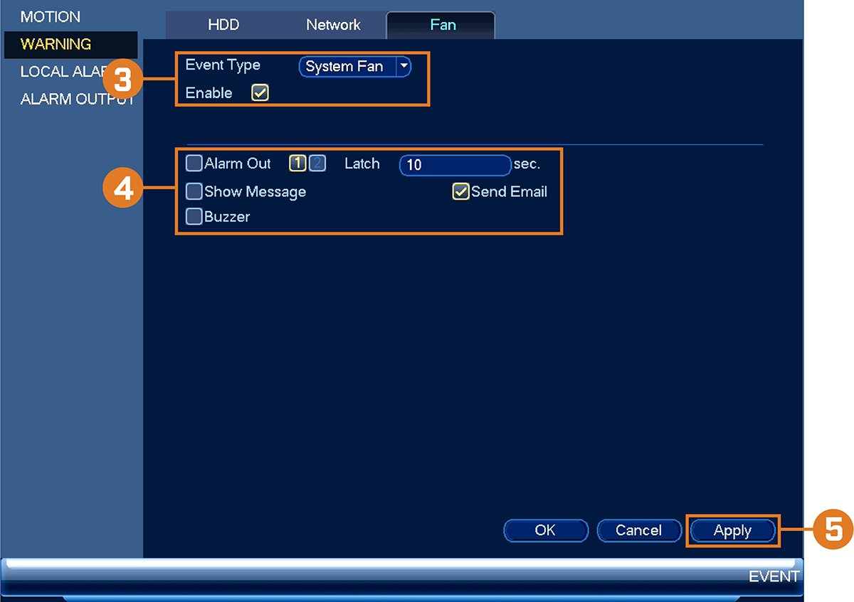
- Check Enable to activate fan warnings.
-
Configure the following for the selected event type:
- Alarm Out: Check the box to activate alarm output devices (not included) when the selected event occurs. Select the alarm output devices that will be activated, then enter the number of seconds the alarm output device(s) will activate after the selected event occurs next to Latch.
- Show Message: Check to show a popup message when the selected event occurs.
- Send Email: Check to enable email alerts. You must configure email alerts before you will be able to receive them (see 16.4.4 Configuring Email Alerts ).
- Buzzer: Check to activate the system buzzer.
- Click Apply to save changes.
To configure fan warnings:
16.4.12 Configuring Alarm Input Devices
You can connect alarm input devices such as motion sensors (not included) or glass break detectors (not included) to the system.
The system can be set to trigger recording or take other actions when these devices are activated.
To connect alarm devices:
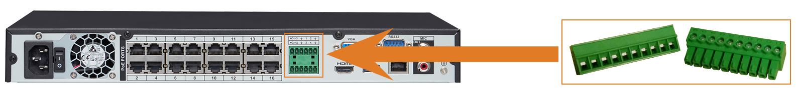
- Connect the included green alarm blocks to the back panel of the recorder.
- Connect your alarm device according to the supplied documentation.
To configure alarm input devices (not included):
- From the Live View display, right-click to open the Quick Menu, then click Main Menu.
-
Click
, then click EVENT. Click the LOCAL ALARM tab on the side panel.
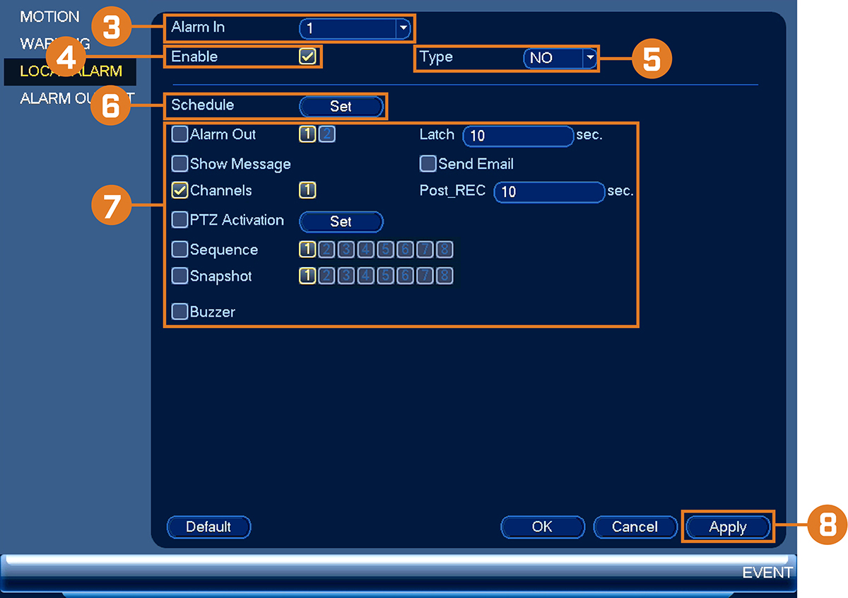
- Select the alarm input port the device is connected to.
- Check Enable.
- Select NO (Normal Open) or NC (Normal Close) depending on the type of alarm input device you have.
-
Click Setup next to Schedule to configure the times of the week when the selected device will be activated. By default, the device will be activated 24/7.
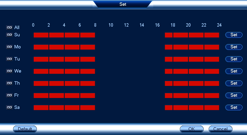
- Click or click-and-drag along each of the red timelines to quickly add or remove time from each day’s schedule in 30–minute segments.
-
Click
 beside 2 or more days to link schedules (
 ). This allows you to quickly change multiple schedules at once.
- To make fine adjustments to a schedule, click Set. This will allow you to set exact start and end times for a schedule.
- Click OK when finished.
-
Configure the following system responses and parameters for the alarm input device:
- Alarm Out: Check the box to activate alarm output devices (not included) when the selected device is triggered. Select the alarm output devices that will be activated, then enter the number of seconds the alarm output device(s) will activate after the selected device is triggered next to Latch.
- Show Message: Check to enable an on-screen pop-up when the selected device is triggered.
- Send Email: Check to enable email alerts. You must configure email alerts before you will be able to receive them (see 16.4.4 Configuring Email Alerts ).
- Channels: Click the checkbox to enable video recording when video loss occurs. You can then select the channels the system will record when video loss occurs on the currently selected channel.
- Post_REC: Enter the number of seconds the system will record after video loss occurs.
- PTZ Activation: Check to enable PTZ actions when video loss occurs (PTZ camera required; not included). Click Set to select which PTZ actions will be taken by each camera.
- Sequence: Check to enable a custom sequence mode when motion is detected on the selected channel. Then click the channels you would like to display in the custom sequence mode.
- Snapshot: Check to save a snapshot.
- Buzzer: Check to enable the system buzzer.
- Click OK to save changes.
16.4.13 Controlling Alarm Output Devices
You can connect alarm output devices (not included), such as sirens or strobe lights, to the system. The Alarm Output menu
allows you to enable or disable alarm output devices and manually an activated device.
To connect alarm devices:
- Connect the included green alarm blocks to the back panel of the recorder.
- Connect your alarm device according to the supplied documentation.
- From the Live View display, right-click to open the Quick Menu, then click Main Menu.
-
Click
, then click EVENT. Click the ALARM OUTPUT tab on the side panel.
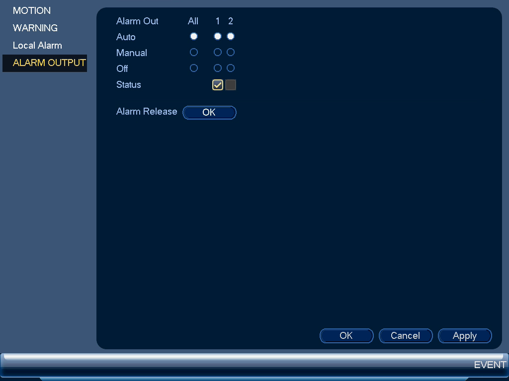
To configure alarm output devices (not included):
- To enable alarm output devices, select Auto or Manual for each device you would like to enable. Select Stop to disable the alarm output device. Click Apply to save changes.
- To manually disable activated alarm devices, click OK next to Alarm Release.
To control alarm output devices:
16.4.14 Configuring Pre-Recording
The system can pre-record video when motion detection events occur. This will ensure that the system records the entire event
when motion is detected. By default, the system pre-records 4 seconds of video every time motion is detected.
- From the Live View display, right-click to open the Quick Menu, then click Main Menu.
-
Click
![icon]() , then click STORAGE. Click the SCHEDULE tab on the side panel.
, then click STORAGE. Click the SCHEDULE tab on the side panel.
![Graphic]()
- Under Channel, select the camera you would like to configure or select All.
- Under PreRecord, select the duration for pre-recording.
- Click OK to save settings.
To configure pre-recording:

16.4.15 Formatting the Hard Drive
Format the hard drive to erase all saved data. If you install a new hard drive, you must format the hard drive using the procedure
below before you will be able to record.
- From the Live View display, right-click to open the Quick Menu, then click Main Menu.
-
Click
![icon]() , then click STORAGE. Click the HDD MANAGER tab on the side panel.
, then click STORAGE. Click the HDD MANAGER tab on the side panel.
![Graphic]()
- Select the hard dive you would like to format.
- Click Format, then click Yes to confirm.
To format the hard drive:

16.4.16 Configuring Hard Drive Type
The system supports the following hard drive types:
- Read/Write: Normal recording hard drive.
- Read-Only: The system can playback data from this hard drive, but it will not record to it.
- Mirror: The hard drive will be used for mirror recording only. You must set up mirroring recording before this feature will work. For full instructions, see 16.4.17 Setting up Hard Drive Mirroring (Advanced) .
To set the hard drive type:
- From the Live View display, right-click to open the Quick Menu, then click Main Menu.
-
Click
![icon]() , then click STORAGE. Click the HDD MANAGER tab on the side panel.
, then click STORAGE. Click the HDD MANAGER tab on the side panel.
![Graphic]()
- Select the hard drive type under the Type column next to the hard drive you would like to configure.
- Click Apply to save changes. The system will restart to complete this operation.

16.4.17 Setting up Hard Drive Mirroring (Advanced)
A mirror hard drive can be used to automatically backup video footage recorded to the recording (read/write) hard drive. When
a mirroring hard drive is installed, the system can be set to record cameras in parallel to both the recording hard drive
and the mirror hard drive. This way, the footage is automatically backed up if the recording hard drive fails.
How hard drive mirroring works:
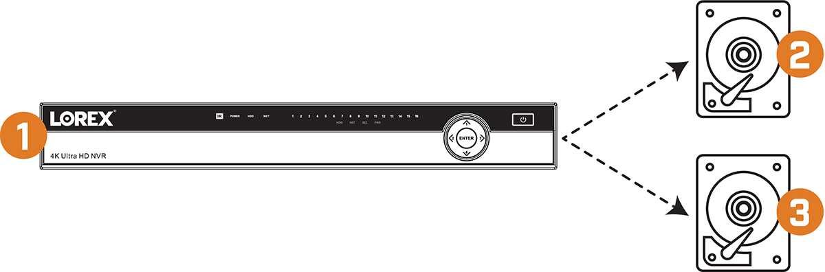
- Security system
- Primary hard drive
- Mirror hard drive
- From the Live View display, right-click to open the Quick Menu, then click Main Menu.
-
Click
, then click STORAGE. Click the HDD MANAGER tab on the side panel.
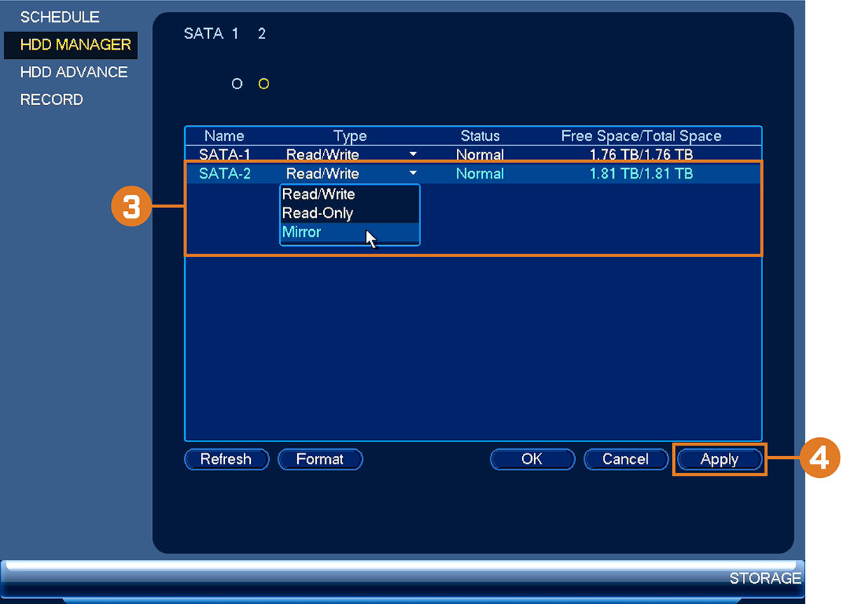
- Click the Type drop-down under the second hard drive and select Mirror.
- Click Apply to apply changes. Click Yes to confirm. The system will format the hard drive and restart.
-
When the system restarts, right-click to open the Quick Menu, then click Main Menu. Click
, then click STORAGE. Click the SCHEDULE tab on the side panel, then Record on the top panel.
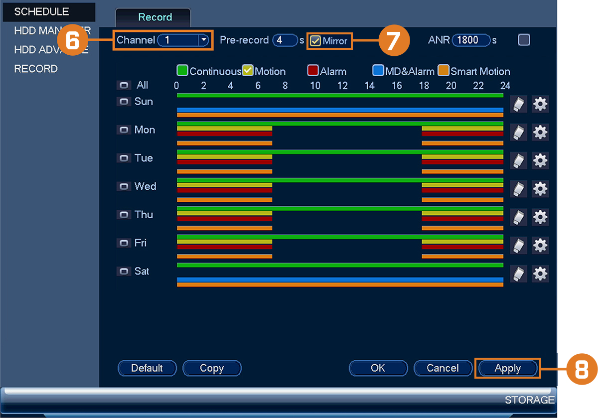
- Under Channel, select the channel you would like to enable for mirror recording.
- Check Mirror. Repeat the process for any additional channels.
- Click Apply to save changes.
To set up hard drive mirroring:
16.4.18 Configuring Hard Drive Groups (Advanced)
Hard drive groups allow you to balance recordings across multiple hard drives. For example, you can record channels 1~4 to
one hard drive and 4~8 to a second hard drive. This can reduce the amount of wear on the hard drives and may extend the life
of the hard drives.
- From the Live View display, right-click to open the Quick Menu, then click Main Menu.
-
Click
, then click STORAGE. Click the HDD ADVANCE tab on the side panel, then click the HDD Setting tab on the top panel.
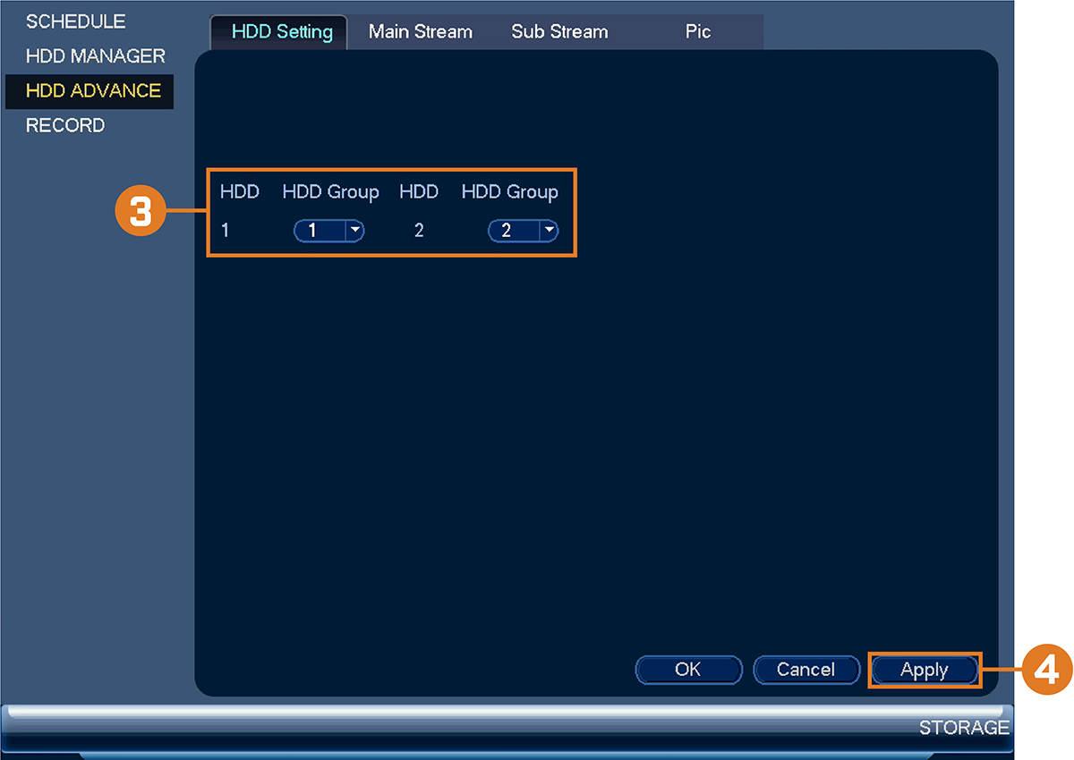
- Under HDD Group, assign a group to each hard drive. To set up two hard drive groups, assign one hard drive to group 1 and the other to group 2.
- Click Apply. The system will restart to apply changes.
- When the system restarts, right-click to open the Quick Menu, then click Main Menu.
-
Click
, then click STORAGE. Click the HDD ADVANCE tab on the side panel, then click the Main Stream tab on the top panel.
-
For each channel, select the hard drive group you would like to record the main stream (high quality) video and then click
Apply.
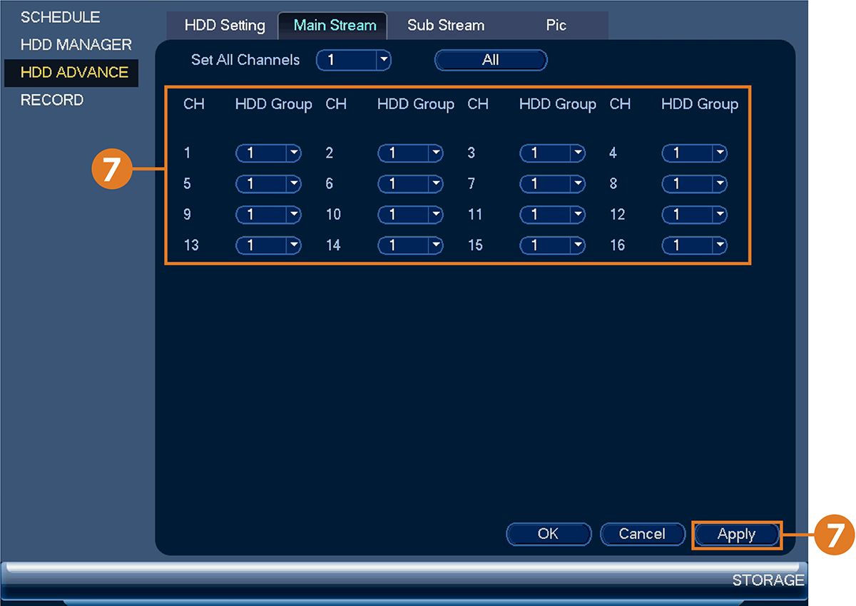
-
Click the Sub Stream tab. For each channel, select the hard drive group you would like to record the sub stream (reduced quality) video and then
click Apply.
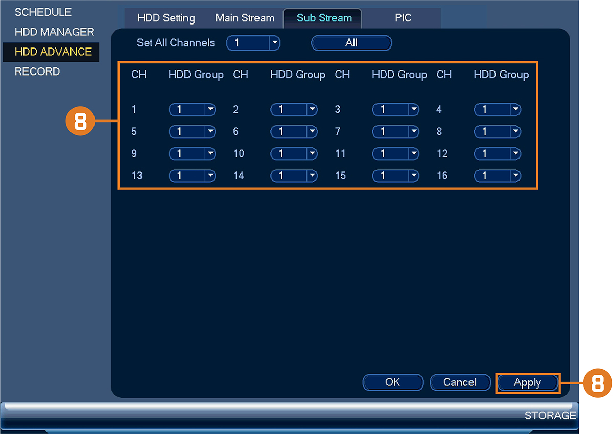
-
Click the PIC tab. For each channel, select the hard drive group you would like to record snapshots and then click Apply.
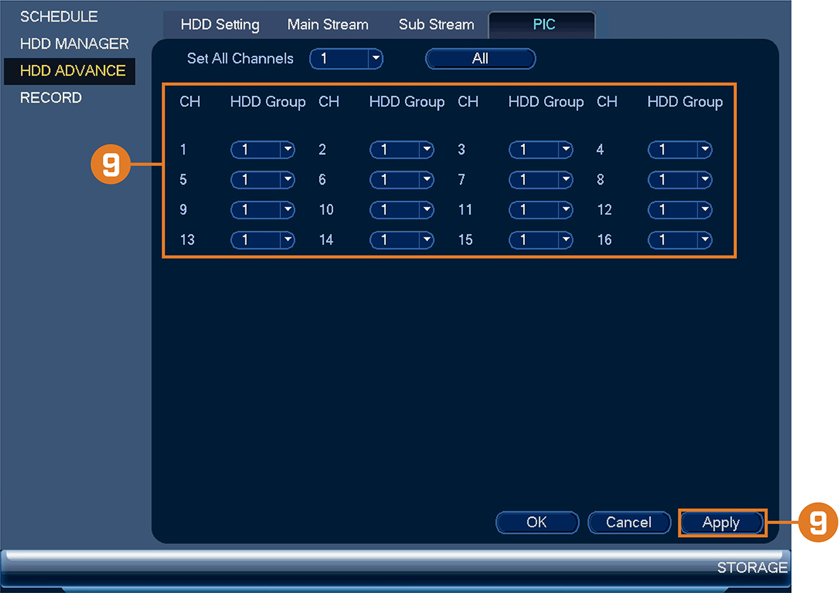
To configure hard drive groups:
16.4.19 Configuring Holidays
You can set certain days as holidays. Holidays have a special recording schedule.
- From the Live View display, right-click to open the Quick Menu, then click Main Menu.
-
Click
![icon]() , then click SYSTEM. Click the GENERAL tab on the side panel, then click the Holiday tab on the top panel.
, then click SYSTEM. Click the GENERAL tab on the side panel, then click the Holiday tab on the top panel.
![Graphic]()
- Click Add Holidays.
-
Configure the following:
![Graphic]()
- Holiday Name: Enter a name for this holiday.
- Repeat Mode: Select Once for the holiday to occur only this year or Always for the holiday to be repeated each year.
- Holiday Range: Select Date to select a specific date, or select Week to select holidays based on which week they fall on.
- Click Add. Now that you have added a holiday, an extra holiday setting is added to the recording schedule.
To configure holidays:


16.4.20 Configuring General System Settings
Configure miscellaneous system settings.
- From the Live View display, right-click to open the Quick Menu, then click Main Menu.
-
Click
![icon]() , then click SYSTEM. Click the GENERAL tab on the side panel, then click the General tab on the top panel.
, then click SYSTEM. Click the GENERAL tab on the side panel, then click the General tab on the top panel.
![Graphic]()
-
Configure the following:
- Device No.: Not supported.
- Language: Set the system languages. Available options are English, French, and Spanish.
- Video Standard: Select NTSC (North America) or PAL (Europe).
- HDD Full: Select Overwrite for the system to overwrite the oldest recordings when the hard drive is full or select Stop Record for the system to stop recording when the hard drive is full.
- Pack Duration: Set the length of time (in minutes) for video files saved to the hard drive. For example, if set to 30 minutes, the system will create a new video file for every 30 minutes of continuous recording.
- Instant Playback: Select the amount of time (in minutes) the system will go back when instant playback is activated in live view.
- Auto Logout: Select the idle time (in minutes) before the system will logout the current user.
- IPC Time Sync: Select how often (in hours) the NVR will update the time on the IP cameras.
- Navigation Bar: Check to enable the Navigation Bar that comes up when you left click in live view.
- Mouse Sensitivity: Use the slider to adjust the mouse speed.
- Click Apply to save changes.
To configure general settings:

16.4.21 Setting the Monitor Resolution (Display)
Configure the system’s monitor resolution and other display settings.
- From the Live View display, right-click to open the Quick Menu, then click Main Menu.
-
Click
![icon]() , then click SYSTEM. Click the DISPLAY tab on the side panel, then click the Display tab on the top panel.
, then click SYSTEM. Click the DISPLAY tab on the side panel, then click the Display tab on the top panel.
![Graphic]()
- Under Resolution, select the correct resolution for your monitor.
- Click Apply to save changes. Click OK again to restart the system using the new resolution.
To set the monitor resolution:

- From the Live View display, right-click to open the Quick Menu, then click Main Menu.
-
Click
![icon]() , then click SYSTEM. Click the DISPLAY tab on the side panel, then click the Display tab on the top panel.
, then click SYSTEM. Click the DISPLAY tab on the side panel, then click the Display tab on the top panel.
![Graphic]()
-
Configure the following:
- Transparency: Select the menu transparency.
- Time Display: Check to show the time on the monitor.
- Channel Display: Check to show the channel names on the monitor.
- Image Enhance: Check for the system to digitally improve the video quality on the live display. This setting does not affect recordings.
- Original Scale: Set the system to show the true aspect ratio of the cameras on the live display. This may add black bars on the top and bottom of the image.
- Click Apply to save changes.
To configure other display settings:

16.4.22 Configuring Sequence Mode
Sequence mode cycles through connected channels to give you an overview of what is happening on all cameras. You can customize the order
that channels appear in Sequence mode, as well as configure which viewing modes should be used.
- From the Live View display, right-click to open the Quick Menu, then click Main Menu.
-
Click
![icon]() , then click SYSTEM. Click the DISPLAY tab on the side panel, then click the Sequence tab on the top panel.
, then click SYSTEM. Click the DISPLAY tab on the side panel, then click the Sequence tab on the top panel.
![Graphic]()
- Choose how many channels will appear on screen when Sequence mode is triggered by motion detection (you must check Sequence when configuring motion detection — see 12 Motion Detection for details).
- Enter the amount of time in seconds that each channel or page will appear on screen during Sequence mode.
- Select a viewing mode to configure. It is recommended to start with View 1 and make your way to View 9. By default, all viewing modes are included in the Sequence mode cycle.
- Configure the order of channels shown on screen for each viewing mode. Uncheck channels / channel groups that you want to remove from the Sequence mode cycle.
- Click Apply.
To configure Sequence mode:

16.4.23 Saving Your System Configuration to a USB Thumb Drive
The system allows you to save your current system configuration to a USB thumb drive (not included). This is useful if you
want to backup your current settings.
- From the Live View display, right-click to open the Quick Menu, then click Main Menu.
-
Click
![icon]() , then click SYSTEM. Click the Config Backup tab on the side panel.
, then click SYSTEM. Click the Config Backup tab on the side panel.
![Graphic]()
- Under Device Model, select the USB device where you would like to save the configuration.
- Click EXPORT to save your current system configuration.
To save your system configuration to a USB thumb drive:

- From the Live View display, right-click to open the Quick Menu, then click Main Menu.
-
Click
![icon]() , then click SYSTEM. Click the Config Backup tab on the side panel.
, then click SYSTEM. Click the Config Backup tab on the side panel.
![Graphic]()
- Under Device Model, select the USB device where the system configuration is saved.
- Click the folder with the configuration file you would like to restore. Configuration file folders are labeled “Config” and then the time and date the configuration was saved (e.g., Config_20140425103727).
- Click Import to restore the system configuration.
- Click OK to confirm. The system will restart to complete the operation.
To restore a saved system configuration:

16.4.24 Restore Default Settings
Restore the system to its default settings.
- From the Live View display, right-click to open the Quick Menu, then click Main Menu.
-
Click
![icon]() , then click SYSTEM. Click the DEFAULT tab on the side panel.
, then click SYSTEM. Click the DEFAULT tab on the side panel.
![Graphic]()
- Check the menus you would like to reset to default settings.
- Click OK.
To restore default settings:

16.4.25 Upgrading Firmware Manually
The primary method for upgrading system firmware is automatically over the Internet. The system also supports firmware upgrades
from a USB thumb drive (not included).
Prerequisite:
- Save the .bin firmware file for your unit onto a USB flash drive (not included), and connect the drive to one of the system’s free USB ports.
- From the Live View display, right-click to open the Quick Menu, then click Main Menu.
-
Click
![icon]() , then click SYSTEM. Click the UPGRADE tab on the side panel.
, then click SYSTEM. Click the UPGRADE tab on the side panel.
![Graphic]()
- Click Browse.
- Click on the .bin firmware file for your recorder.
- Click Start.
To upgrade firmware manually:

16.4.26 Automatic Firmware Upgrades
Firmware upgrades provide enhanced functionality. The system will automatically check for firmware upgrades if it is connected
to the Internet.
- From the Live View display, right-click to open the Quick Menu, then click Main Menu.
-
Click
![icon]() , then click SYSTEM. Click the UPGRADE tab on the side panel.
, then click SYSTEM. Click the UPGRADE tab on the side panel.
![Graphic]()
- Ensure Automatically Check for Updates is checked. If it was previously unchecked, click OK to save changes.
- Click Check for Updates to check for a newer firmware version.
- If a newer version is found, click Upgrade Now to upgrade the system.
To configure automatic firmware upgrade:

16.5 Shutdown
Shut down, restart, or log out of the system.
- From the Live View display, right-click to open the Quick Menu, then click Main Menu.
-
Click
![icon]() , then click SHUTDOWN.
, then click SHUTDOWN.
-
Select one of the following:
![Graphic]()
- Logout: Log out the account that is currently active.
- Shutdown: Power off the system.
- Restart: Power off the system, then restart.
To access the shutdown menu:
